Let’s talk about MIM.
Editor’s Note: This article kicks off a series that takes an in-depth look at MIM manufacturing, and how the technology was adopted by Smith & Wesson to produce firearms. Along the way, we’ll also peek at the CNC manufacturing revolution, and the host of improvements made to the basic, S&W revolver design over the last 30 – 40 years. The series will get a little technical at times, but if you hang in there, you’ll get an insight into modern revolver manufacturing that you won’t find anywhere else. Thanks for joining us on the journey. –Mike
MIM, which is an acronym for Metal Injection Molding, is one of those terms that comes with a lot of baggage. Even though it’s just a manufacturing process—and a useful one, at that—it tends to trigger a significant emotional reaction in the hearts and minds of many RevolverGuys, who have come to distrust and dislike both the process and its products . . . even if they’re not exactly sure, why.
There’s a lot of misunderstandings about MIM in our gun community, most of which are rooted in a lack of knowledge. We think we know more about MIM than we actually do, but the truth is that a lot of what we “know” about MIM is either incorrect or dated, and our ignorance leads us to flawed conclusions about today’s MIM-manufactured products.
Straight to the Source
That just won’t do, so RevolverGuy sought help from experts in the field to help explain the mysteries of MIM, and answer our questions about the pros and cons of the method.
Fortunately, our contacts introduced us to several members of the Smith & Wesson Revolver Engineering Team who helped to transform the Springfield operation during the 1990s and early 2000s, by replacing older methods of manufacture with emerging technologies like CNC machining and MIM. In turn, they introduced us to some of the leading MIM manufacturers in the industry.
With their help, we’ll dive into MIM to understand it better, and develop a more balanced view of its strengths and weaknesses, compared to other forms of manufacturing. In this first part, we’ll talk about the basics of the MIM process, then in succeeding parts we’ll discuss the pros/cons of MIM, and the S&W Revolver Engineering Team’s experience with integrating MIM manufacturing at Smith & Wesson.
Are you ready to get your engineering cap on? Good. Let’s go!
What, exactly, is MIM?
The “Forty-Thousand Foot view” of Metal Injection Molding (MIM) goes like this.
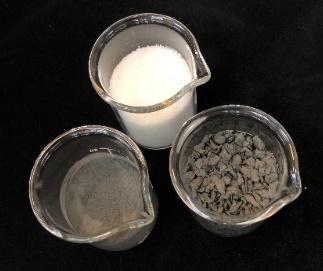
Metal powders are mixed with a wax binder to form a kind of metal feedstock, which is then loaded into special machines containing molds. The machine fills the molds with the feedstock to create a part with the consistency of a crayon, and these parts are then heated, or dipped in solvent, to remove the binder. The resulting part, which now has the consistency of a cross between crayon and chalk, is then placed on a special tray and heated in a furnace to transform it into a solid metal piece, which can then be further hardened and tempered with an additional heat treatment.
That sounds pretty simple in concept, but the process is actually quite complex, in execution. It takes a lot of work and expertise to perfect and manage this manufacturing process, and it’s not a method for a manufacturer who’s looking for the easy way out. Sometimes, it can be much easier and cheaper to machine metal than to create the same part via a MIM process.
I know this runs counter to the mistaken beliefs shared by many people in the gun community, but it’s true. To help explain why, let’s dig a little deeper into the MIM manufacturing process.
First, The Homework
The first step of any manufacturing process is to define what the finished product must do. Once an engineer understands the task that the product must accomplish, they’ll have a better understanding of what it needs to look like, what it needs to be made of, how it must perform, and how it can be made.
The question of which manufacturing process will be used to make the part is usually answered by the part, and the task it’s required to perform. Some parts can be made using inexpensive materials and inexpensive manufacturing processes, because the job isn’t very demanding, but other parts may require more expensive materials and manufacturing processes, by virtue of the tasks they’re required to perform. The trick is to match the material and manufacturing process to the job.
If a stamped part, made from inexpensive low-carbon steel, will do the job well, then it would be foolish to machine that same part out of titanium, right? The latter material and manufacturing process would be much more expensive, and would produce a part that needlessly exceeds the requirements of the job, so it would be a bad choice to build it that way.
In contrast, if a part is required to perform a difficult job, that can also eliminate certain materials and manufacturing processes from consideration. Centerfire caliber revolver cylinders, for example, must withstand extreme pressures, so they’re typically made from robust materials like forged steel or machined steel billets. Other materials and manufacturing methods (like compressed metal powders and cast steels) are less appropriate for this job, by virtue of their properties, so they’re not considered, even though they might cost less. The porous nature of a casting, for example, creates potential, hidden weaknesses that you wouldn’t want in a pressure vessel that must withstand centerfire caliber pressures, so you wouldn’t use that material and process for the job.
So, what does this have to do with MIM?
It’s a way of explaining that when a manufacturer decides to make a part using MIM, it’s normally the result of a very careful examination of all possible methods and materials, not simply a shortcut to save money. As we’ll discuss more, in a bit, making parts via MIM can be a complicated and expensive process, and it’s not a decision that’s made lightly. There may indeed be some cost savings with MIM manufacture in the long run, but the up-front costs are considerable, and wouldn’t be worth the expense if the part didn’t provide equal or better performance than parts made from other materials and methods.
A smart manufacturer doesn’t say, “let’s make ‘X’ with MIM,” they ask, “what is the best way to make ‘X’,” and if the answer is MIM, then that’s what they do.
Molding
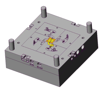
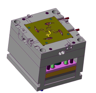
Once it’s been decided that MIM is the best way to manufacture a part, creating and perfecting the molds that will be used to manufacture the part becomes the first major task to accomplish.
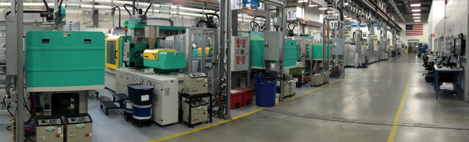
MIM molding machines are basically, upgraded, beefed-up, plastic injection machines. The molds used in MIM molding machines might have slightly different hardware, but the design concept is essentially the same between plastic and metal injection molds.
There’s a lot of things for a MIM mold-maker to consider, though, and it’s not an easy job to build a good mold.
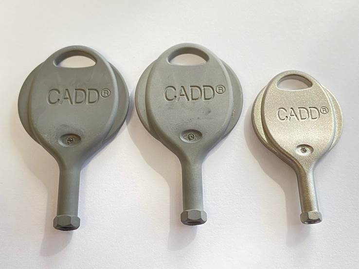
To start with, because shrinkage occurs during the MIM process, the molds must be larger than the dimensions of the finished part. If you knew exactly how much shrinkage would occur during production, then you could build a mold that was exactly that much larger, but one of the challenging things about MIM, is that you can’t determine shrinkage with that level of precision, ahead of time. If you have some prior experience with your formula and process, you can get pretty close, but nailing it exactly on your first try is a difficult target, indeed.
So, engineers oversize a mold to provide for the expected shrinkage, but if the MIM process actually delivers a different amount of shrinkage during testing, they have to evaluate whether or not they can tweak other parts of the MIM process to get the desired result, or if they have to go back and modify or redesign the mold.
For example, engineers might design a mold that is 21% larger than the desired dimensions of the finished part, expecting to have a shrinkage rate somewhere between 20.5% and 21.5%. If the parts that come out of the mold during testing are a little too big, or a little too small, they might look to change the recipe of the feedstock (more or less binder-to-powder ratio), or processing conditions (i.e., change the time or temperature in the furnace), to get the desired result with the same mold. However, if these changes to the process can’t deliver a part that’s within specs, then the mold may have to be modified, or even replaced
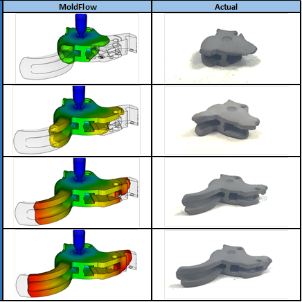
Besides shrinkage, flow properties must be considered when making molds, too. A MIM mold incorporates a gate, through which the MIM feedstock is introduced into the mold, and the feedstock has to flow through the gate in a manner that allows it to completely fill the mold without bubbling. If turbulence develops inside the mold, it could interrupt the flow of feedstock to a portion of the mold, and result in a gap or void that would affect the final shape or strength of the part. So, engineers spend a lot of time perfecting the location of the gate, and the interior shape of the mold, to ensure the feedstock fills all the nooks and crannies with reliability and no bubbles.
The gates must occasionally be recessed in the mold, because the finished part cannot have a raised bump where the gate was located, to avoid drag and reduce the potential for snags. Too, the gate must be carefully positioned so that the gate mark, which is left behind on the part, is located where it won’t interfere with the function of the part, or be visible as a cosmetic flaw (sometimes, on cosmetic parts, the gate marks are simply machined off later, to eliminate any trace of them).
The same goes for the pins which will be used to eject the finished part from the mold. The pins must be located in the mold where they won’t leave their telltale mark near a functional or cosmetic surface.
So, there are definite engineering challenges associated with designing a mold, and fine-tuning the process that will deliver an in-spec part with that mold. Obtaining a quality, finished part starts with a good mold design, which is why so much effort (and money) is spent in this earliest stage of MIM production.
Compounding
Once you have a good mold in hand, then the process of “compounding”—developing the exact “recipe” for the required MIM slurry—can begin.
The metallurgists have previously defined what properties the material must have for the job (strength, ductility, surface smoothness, etc.), so now the task is to figure out what mix of metal powders will deliver them.
Metal powders are formed by melting steel and atomizing it, which is achieved by blasting it with something like water, or various gasses. Powders can be different shapes and sizes, depending on the material and the process used to atomize them. Some are spherical (like planets), for example, while others are shaped like random interlocking crystals (like asteroids).
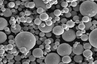
With the objective in mind, powders are blended together to obtain the desired qualities of the final part. With hammers and triggers, for example, you want great strength, but also some ductility (because a brittle part would shatter), and a very smooth surface, so you have to carefully blend your powders to achieve this.
The powder blend will be mixed and grated with a wax binder to create a material that’s the consistency of a shredded cheese. This feedstock blend will be the raw material that will later go into the molds, in the next step of the process.
As previously mentioned, one of the greatest challenges of MIM manufacture is controlling shrinkage. As we’ll discuss in more detail later, all MIM parts will shrink during the sintering process, and proper compounding is the first step in controlling the rate of shrinkage, and making it repeatable, over time.
Once the recipe is nailed down, any deviations from the recipe can change the final result, so the companies that excel in this portion of the industry, and develop the best reputations for consistent quality, are those that are highly disciplined.
Debinding
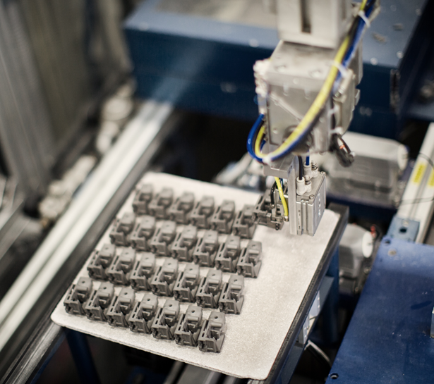
Once you have a mold and a powder-binder feedstock, you can start making parts.
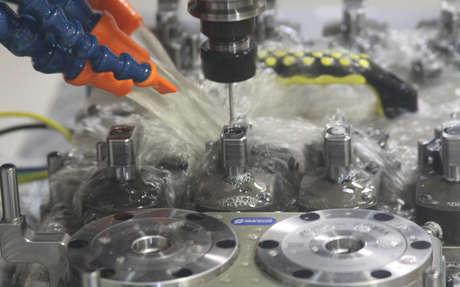
As previously mentioned, the shredded cheese-like feedstock is loaded into a MIM molding machine that contains the mold. The machine fills the mold with the feedstock, and when the machine is done with its work, you have an oversized part with the consistency of a crayon. In industry jargon, this is called a “green” part
This crayon-like green part is now ready for debinding, which is the process of removing the wax binder from the part.
Parts are debound in one of two ways: Either by using heat to melt the wax out of the part, or; By submerging them in a solvent, which melts and extracts the wax from the part. The time that a part will be heated or dipped, the temperature of the furnace or tank, and the type/composition of the solvent are all proprietary variables that the manufacturer will control to achieve the desired result.
Thermal debinding usually takes about 24-48 hours, whereas the solvent process takes about 4-12 hours, depending on the cross sectional thickness of the part. When the process is finished, the part (which has now become a “brown” part, in industry-speak) has a porous, chalk-like consistency, and is very brittle. Extreme care must be used when the part is readied for the next step, sintering, to avoid damaging it.
Sintering
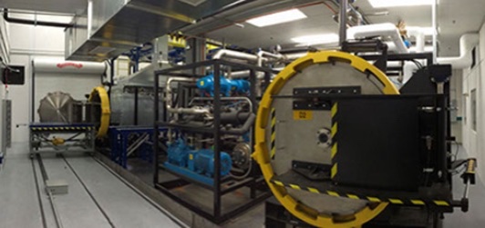
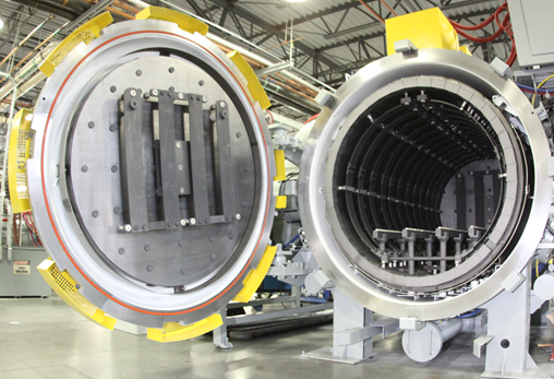
The chalk-like, powdered metal part is transformed into a solid, hardened metal part in the sintering stage, by subjecting it to extreme heat, which melds the powdered metal together.
After debinding, the chalk-like part is placed on special trays, made of graphite or ceramic, called “furniture.” The furniture will support the part as it shrinks in the heat of the furnace, which operates around two-thousand degrees, Fahrenheit.
Warping, or distortion, is a critical concern in this stage. If the shrinking part is not properly supported by the furniture, as it slides across its surface, then it can sag or catch and the finished part will be misshapen or have drag marks. To combat this, MIM manufacturers use a variety of techniques, such as giving the furniture a smooth, snag-free surface that allows the part to glide across it, as it shrinks.
The time and temperature in the sintering furnace are important variables that must be controlled to get the desired amount of shrinkage. During the testing phase, engineers might experiment with changing time and temperature (as they did with compounding changes) to fine tune the shrinkage of the part, and “dial in” the mold perfectly, but once these variables are finally nailed down, they become part of the manufacturing recipe, and cannot be changed. Consistency and quality comes from following the recipe.
Heat Treatment
Some MIM parts will be ready to use after sintering, but others may require additional heat treatment to obtain the desired level of hardness.
In this stage, the sintered MIM part will be placed into a heat treat furnace and go through a hardening and tempering process similar to that used for any metal part. When this final stage is completed, the part is sent off to final inspection, to check the metallurgy and verify that it is dimensionally accurate.
Play it again
We described the molding, compounding, debinding, sintering and heat treatment process so you could understand the stages in MIM manufacturing, but it’s important to remember that it takes a while to get all of these elements ready for production.
When the team is getting things ready for prime time, they often go through many cycles and iterations of this process, which can become very intense. The team engineers the mold based on expected shrinkage rates, conducts flow analysis, builds a mold, does their compounding, then builds their prototype parts.
The prototype parts are thoroughly inspected and analyzed, even x-rayed, and are then shot in test guns to see how they function and wear–sometimes to the tune of thousands and thousands of rounds. Oftentimes, the parts are cut open to examine them and conduct metallurgy tests.
Any negative findings could result in additional changes to the mold, the compounding, or any other stage of MIM manufacture (debinding, sintering, and heat treatment), and the process repeats until a perfect part is created—one that meets all the requirements for function, appearance, hardness, durability, and proper tolerances.
Working through this development process often takes two, or possibly three, attempts to get it right, and can take as long as six to twelve months. The costs can mount quickly, with a mold for a single small part, like a hammer or trigger, costing up to $150K to develop.
Not Easy
If you multiply that time and expense by all the small parts in a revolver’s action that you might want to MIM, you begin to understand what a daunting task it can be to make the change to this style of manufacture.
The MIM process is both complicated and expensive, and requires a total commitment to do it right. MIM is not the playground for companies that want to cut corners or do things on the cheap.
We’ll talk more about their personal experience with MIM in a future installment, but for now, it’s important to understand that a company like Smith & Wesson wouldn’t “go MIM” just because they thought it would save some money. They would only go through the substantial effort and expense if they thought it was the best way to manufacture their product.
It would have been a lot easier for the Revolver Engineering Team to keep on doing things as they had been for a hundred years already, when they considered overhauling their manufacturing process in the early 1990s. Yet, their thorough exploration of the advantages and disadvantages of MIM convinced them it was the right move.
We’ll take a look at those advantages and disadvantages in the next part of this series. Please come back and check it out, here at RevolverGuy.
*****
RevolverGuy would like to thank Craig Mariani (the former Team Leader of the Smith & Wesson Revolver Engineering Team) and Norm Spencer (a Smith & Wesson Machinist, Model Maker, and Manufacturing Engineer) for their assistance with this project. The education they provided was critical to our understanding of MIM technology and the manufacturing changes that occurred at Smith & Wesson during their tenure. We would also like to thank the team at ARC Group Worldwide, for their information and assistance. Thank you, gentlemen, for sharing your experience and knowledge with us!
Fantastic article!
I sent my daughter’s new production S&W Model 10 Classic to Frank Glenn a few years ago for his S&W action job. I wasn’t sure what to expect as the gun of course includes MIM parts.
What came back was a revolver with a double action trigger pull so flawless, yet reliable with all primer types, that I decided to quit worry about MIM and trust that the engineers that design the parts and the gunsmiths that refine the parts know what they’re doing a lot more than I do. She shoots the daylights out of the gun and it never misses a beat.
That’s a super report, Brent! You’re fortunate to have had Frank work on the gun. It’s a shame he’s winding things down.
A good MIM part can certainly be improved/smoothed by a knowledgeable ‘smith
Ah, a new piece to digest! I was afraid RevoverGuy had gone the way of the dodo, but you guys turned out to be as strong and durable as a properly applied MIM part.
Thank you Bill!
Thanks for undertaking this weighty topic, Mike. I think there are a lot of misconceptions and biases about MIM in the gun world that could use clearing up. And I look forward to learning some things along the way.
Thanks Hammer! I’m excited to share Parts II, III, and IV. I think we’ll definitely challenge the MIM orthodoxy that’s taken hold of the gun culture.
I sit and read, and re-read, and smile. Mike put a LOT of time into this entire project (measured in months), and has probably been one of the most research intensive articles to appear here. Congrats and El Grande Thanks for your efforts. It’s value is only lost on those not willing to appreciate and embrace technological advancements.
The naysayers in the firearms community who have, for years, ragged on companies for using MIM parts need to read this article, and do some research of their own, sit back and relax. Yes, the S&W .357 Combat Magnum of 2022 is not like the .357 Combat Magnum of 25 years ago, and yes, many of the parts will not interchange due to engineering changes. But overall, the guns produced by the manufacturers today are far more sophisticated in their precision and parts compatibility than at any other time period.
Smith & Wesson was not the first to use MIM parts in guns, but has been a pioneer in wholesale redesign of an entire engineering process of gun manufacturing. Ruger also has gone to MIM parts with considerable improvement in fit and performance.
BTW, readers, if you have an automobile built after @ 2015, the number of MIM parts in your engine and drive train would surprise you !
Thank you Sir! This was indeed an intensive effort that spanned many months, and I learned a WHOLE LOT along the way—things that definitely challenged my understanding and appreciation for this technology. I’m excited to share more of what I learned in the upcoming installments!
BTW, jet engines are full of MIM parts, too!
This is the best, and most detailed, explanation of MIM firearms parts I’ve encountered so far. Though I’m somewhat on the fence about that technology, it’s important to keep an open mind about the process, especially in regard to the allegations that MIM is a cheap and easy manufacturing method that produces substandard stuff. If used appropriately, MIM should perform quite well, perhaps even better than older techniques.
Thanks Spencer, that’s much appreciated. Our experts were very helpful in teaching me about this technology, and I’m grateful for their help in making this series so comprehensive and accurate. I look forward to sharing more of it. It’s going to be a fun and educational journey.
Awesome info. Thanks for putting this together. I excited to see the later parts of this series.
First of all “Revolver Guy” is fantastic! The articles are so well written and engaging. I’m working my way through all the articles a pleasurable and profitable pursuit.
A definitive article on MIM is so needed as many of us don’t fully understand the product but may have strong opinions on the subject. This project may affirm or dissolve those opinions.
The claim made in defense of MIM parts is that they’re used in aircraft engines. My understanding is that all those parts are subject to X-Ray before being used, I don’t think gun parts get the same attention.
I recently had a firing pin break on my 642, fortunately I had a replacement on hand that was a hardened steel, machined firing pin from a aftermarket supplier.
Looking forward to the upcoming articles on the subject. Thanks for you efforts in getting the facts about MIM out to revolver lovers.
Thanks Gene, I’m so glad you’re enjoying the site!
Yes, jet engines get magnafluxed, x-rayed, MPI’d, the whole bit. Certainly not appropriate for guns, but it does show that MIM parts are durable in some incredibly harsh environments.
Re: your failed firing pin, that’s not a MIM part on the 642, just for the record. I wouldn’t want any readers to misunderstand your comment, and think that. It was just a machined part made of material that wasn’t durable enough, or wasn’t machined well, like we saw with some of the early Kimber Ti firing pins. I’m glad you had a better substitute on hand, to replace it.
We’re excited to tell more of the MIM story in future parts. Stay tuned for more!
I’m really looking forward to the rest of the series. What an interesting, and complicated way of manufacturing. Thanks for delving into this; I’m hoping it will dispel some of my biases (though I will always appreciate a nicely machined piece of steel).
Me too, Conrad! If it makes you feel any better, you can still machine a Mim’d steel part, after sintering. ; ^ )
Brilliant informative article.
It’s remarkable the similarities between the MIM process and Porcelain and some ceramics.
Incredible minds at work making such concepts into reality and cost-effective common place use.
Thanks Todd! We’re just getting started. Make sure to come back for Parts II-IV!
Excellent piece, Mike. It not only helps address “lore” about MIM parts but also serves as a model for good technical writing. I taught that subject for several years. A fundamental concept in the field: specialists who write for nontechnical readers (end users, shareholders, customers, investors, journalists, attorneys) need to grasp how to decode technical terms and processes.
You might discover a tech writing teacher using your series in an E-School somewhere. Will need a “trigger warning,” quite literally 😉
Mike, not sure my first post on this went through, but you’ve accomplished a goal that I taught for years to technical-writing students: make a complex idea understandable for non-specialists.
I think you have already debunked some “Lore” about MIM parts. Thanks!
Thank you Sir! Received them both, and I’m doubly appreciative of the kind words! I’m eager to share the rest of the series in the coming weeks—I think we’re gonna turn some heads about MIM and its potential. I know that my opinion of it changed dramatically, as I became more educated on the subject. I’m glad I was able to gain access to some true experts, and share their knowledge and experience with our audience.
Mike:
What an excellent piece of research and, as usual, a well written article that explains one of the mysteries of modern manufacturing. I agree with “ol+wheelgunner” about your technical writing skills. I spent several years in the aerospace industry writing and reading technical articles. I know your writing skills are superior.
I’m an “old duffer” who doesn’t like change. I’ll continue to prefer guns made from forged and machined steel with walnut stocks, but you have done an excellent job of dispelling the myth that this new manufacturing process, MIM, turns out sub standard parts.
Thank you!
Dick
Thank you Sir! I’m humbled. Honestly, I prefer my older guns too, but the MIM no longer turns me off, like it once did. The lock? Well, that’s a completely different ball of wax . . .
Another great article Mike! It is easy to fall into the mindset that MIM parts and MIM guns are inferior to their forged ancestors, but your article does a great job explaining how the technology has changed and how it works. I have been relying on MIM S&Ws for quite a while now and I have yet to experience any problems.
That’s great to hear, Mark. I’m glad those guns have been treating you well. We’re seeing everyone go to MIM, to some degree. You’ll find MIM parts inside of Ruger and Colt revolvers as well, these days. No avoiding it.
Sir, this article is fascinating! Were I twenty years younger I’d want to go back to school and get involved in engineering this stuff… instead I’m thinking gunsmithing in retirement. Which, of course, is not a bad thing either. Thank you.
Thanks Riley! If I promise you another three parts, can I reserve a spot in line for your gunsmithing talents? A good gunsmith is harder to find around here than a good brain surgeon!
Yes indeed! I think a smith specializing in revolvers will be in demand! I’d be pleased to work on yours as needed!
Riley, did you see that Cylinder & Slide just announced they were closing? Bill Laughridge is retiring. I’m a little stunned that there was no succession plan. More room for you to hang out your shingle!
Great article!…
I know I’m late to the party, but wanted to thank You for all the hard work and research that went into this story. Ignorance leads to foolish, and often bad conclusions. Your efforts at educating us are greatly appreciated! Thanks, Mike…I’m looking forward to the following posts!
I appreciate it Kevin! Part Two runs on Saturday!
Mike, I’m a little late to this party but the subject was recently resurrected on the S&W forum. I was an LE guy for S&W when they introduced the MIM process to their manufacturing process. Some of us were a bit concerned at first but those concerns eventually faded. It was customary for us to do an occasional repair in the field and we saw zero increase in parts failure with MIM parts. I even built a PPC revolver with a model 65 using MIM parts. That gun tuned up beautifully and has thousands of rounds downrange plus a ton of dry firing without a single parts failure. I did retime it with a new hand at about 25k rounds and took out the end shake at the same time, but that’s pretty much it. I do a lot of revolver tuning in the area I live and have no issues with MIM parts. Keep up the great work Brother!
Thanks Taj! Great to hear from you, and I appreciate you sharing your expertise on this subject with us!